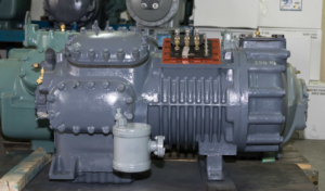
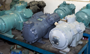
Initial Process
Each incoming compressor block is inscribed with a job number and all operations performed on it is recorded on a computer database.
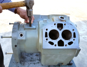
The first process is to drain the oil completely and dismantle the compressor. The components are examined, measured for size and tolerance using micrometers and cylinder bore gauge.
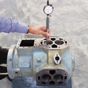
Mechanical Operations
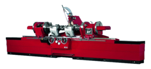
Crankshaft grinding machine
Worn out crankshafts are ground to make them undersized by 0.25 and 0.50mm.
Cylinder block re-boring machine
The compressor’s cylinder bore will be re-bored to make them oversized by 0.25 and 0.50mm.
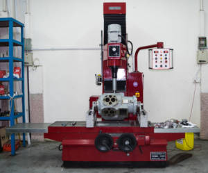
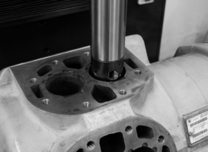
Cylinder block Honing machine
The re-bored cylinder bore will be honed to improve surface texture.
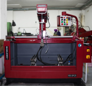
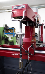
Valve plate surfacing machine
The unfinished valve plate will be re-surfaced for better overall compression.
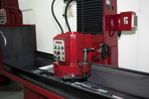
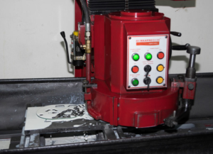
Connecting rod re-boring machine
Connecting rods will be re-bored according to the diameter of the crankshaft for a best fit.
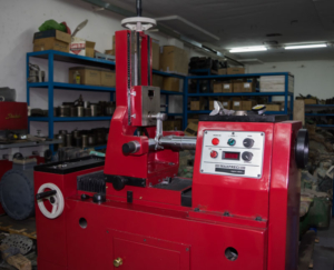
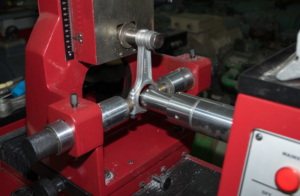
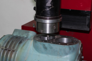
Milling machine
The cylinder bores are milled to improve shape if needed near the reed valves.
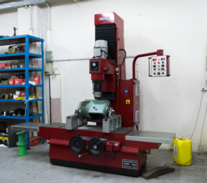
Lathe machine
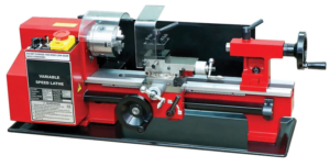
The lathe machine is used as a general purpose tool to refine certain components of the compressor.
Other Operations
The components of the compressor are thoroughly washed using a spray wash machine to get rid of dirt and other contaminants.
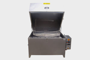
Spray wash machine
Rewinding Process
The stator winding is removed from the compressor and sent to the rewinding division which includes coil cutting/extracting machines and coil winding machine.
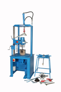
Coil cut-off/extracting machine
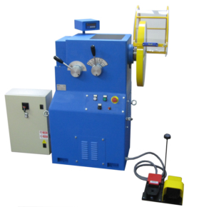
Coil Winding machine
Coils are pulled out from the stator using the coil extracting machine and are measured using a micrometer. Subsequently, the number of turns in coils is noted.
The rotor and stator are cleaned. The coils are wound using the coil winding machine and later inserted manually by hand incorporating class H insulation and dipped in Freon-proof varnish.
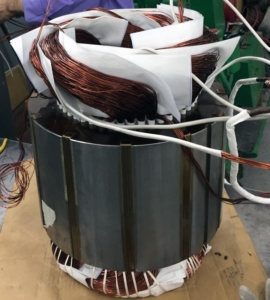
Rewound compressor motor
After varnish, the stator is kept in an electric curing oven for twelve hours at a temperature of 120.C for dry.
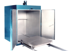
Electric curing oven
Each winding is then subjected to 2,000 DC voltage to earth test using a high voltage DC tester. Ohm readings are taken with multi-meter and low voltage phase balance is tested by variable speed voltage transformer. All measurements are recorded.
Windup
- The compressor is reassembled by one of our experienced technicians and checks are made at every stage of assembly.
- After assembly, the compressor is bench-tested electrically with an ammeter and ohmmeter.
- Amp readings are taken to ensure that the three phases are balanced.
- Oil pressure is taken whilst the compressor is run clockwise and again when the compressor is run counter clock-wise.
- Oil return is checked via the sight glass.
- Any unloading is checked for correct operation.
- When the compressor has reached a minimum of 10bar head pressure, it is stopped and then restarted.
- A pump down test is carried out to ensure there is no let back across the discharge valve reeds.
- The compressor is then charged with 30bar Oxygen-free Dry Nitrogen and submerged under water to ensure that it is leak tight before being dehydrated and evacuated.
- The compressor is then given a 2bar holding charge of OFN before being spray-painted in manufacturers original color.
- Finally, the compressor is set and ready to be delivered to the intended client.
Rebuilt compressors
